Introduction
Industrial control valves, pneumatic actuators, and brake chambers rely on rubber diaphragms to transmit pressure while maintaining reliable sealing. Repeated pressure cycling and reciprocating strokes expose these components to both static clamping stress and dynamic bending stress, increasing the risk of fatigue, leakage, and premature failure. Designing custom rubber diaphragms for pneumatic valves therefore requires careful coordination of geometry, material selection, operating conditions, and molding processes.

4 Critical Design Factors for Pneumatic Valve Diaphragms
Reliable pneumatic valve diaphragm design begins with matching the working geometry to the required force, stroke, sealing conditions, and operating cycle.

Factor 01 Effective Working Area & Convolution Profile
The effective working area determines how pressure difference translates into force, approximately following the formula below, while convoluted or rolling profiles control diaphragm deformation throughout the stroke. Longer-stroke applications may require deeper convolutions or optimized rolling geometry to accommodate movement without excessive stretching, unstable motion, or increased hysteresis.
The force generated by the pressure difference can be approximated using the following equation:


Factor 02 Bead & Clamping Edge Design
The diaphragm bead or clamping edge must match the valve housing, groove dimensions, clamping tolerances, and specified compression to maintain reliable sealing. Flat edges, raised sealing beads, and groove-located profiles offer different advantages, so designers should prevent leakage without introducing excessive compression, uneven clamping loads, or edge tearing.
Factor 03 Dynamic Flex Area & Stress Concentration
The dynamic flex area experiences repeated bending and is therefore particularly vulnerable to fatigue-related failure. Designers should maintain appropriate wall-thickness uniformity, incorporate smooth radius transitions in CAD models, and avoid abrupt changes in section thickness that concentrate stress. Prototype testing should confirm that the diaphragm moves without localized stretching, folding, or premature cracking.
Factor 04 Pressure Load & Stroke Requirements
Working pressure, pressure differential, maximum stroke, and cycling frequency must be evaluated together because they determine the diaphragm's loading conditions and deformation behavior. Engineers should verify that the selected geometry and compound can withstand the required pressure range and repeated movement without excessive strain, permanent deformation, or premature fatigue. Where operating conditions vary significantly, testing should cover representative pressure and stroke combinations rather than relying on a single static pressure rating.
Reinforced & Integrated Diaphragm Structures for Demanding Conditions
When operating pressure, dimensional stability, or assembly requirements exceed the capabilities of a basic rubber diaphragm, reinforced or integrated structures may provide a better solution.
Fabric-Reinforced Rubber Diaphragms
Polyester, nylon, or aramid reinforcement can improve dimensional stability and load resistance when the fabric type, weave, and placement match the application. The molding design must allow adequate rubber penetration and bonding while keeping the reinforcement properly positioned, because wrinkles, eccentric placement, or insufficient rubber cover can create weak areas under pressure cycling.
Rubber-to-Metal / Rubber-to-Plastic Bonding
Overmolding rubber around a metal or plastic insert can integrate mounting features, reduce separate assembly operations, and simplify diaphragm installation in pneumatic equipment. Reliable bonding depends on insert positioning, surface preparation, compatible bonding systems, and controlled molding conditions, while the finished assembly must be checked for bond integrity and suitability under its actual operating loads.
How to Select Rubber Materials for Pneumatic Valve Diaphragms
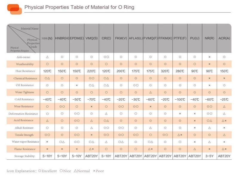
Material selection should reflect the working medium, temperature range, pressure, environmental exposure, and expected fatigue life rather than relying on a generic material ranking.
|
Rubber Material |
Typical Selection Considerations |
|
NBR |
Suitable for many oil-exposed pneumatic systems where oil resistance and cost effectiveness matter. |
|
HNBR |
Worth evaluating for applications requiring improved heat resistance, aging resistance, and mechanical durability. |
|
EPDM |
Often suitable for weather-exposed equipment and compatible oil-free media, subject to chemical compatibility. |
|
FKM |
Useful where higher temperature resistance or compatibility with specific chemicals is required. |
|
FFKM |
A specialized option for demanding chemical or thermal environments where its performance justifies the cost. |
The exact compound, hardness, and formulation can significantly affect flexibility, compression behavior, and fatigue performance, even within the same rubber family. Engineers should confirm compatibility with the actual gas, lubricant, cleaning agent, and temperature range before approving a material for production.
Rubber Diaphragm Molding Considerations for OEM Production
A design that performs well in CAD must also be manufacturable with consistent wall thickness, controlled flash, and repeatable dimensions.
|

|

|
Choosing the Right Molding ProcessCompression molding can suit many conventional diaphragm geometries and may offer a practical balance between tooling cost and production requirements, while transfer molding can be considered for insert-containing structures that require controlled compound flow. Injection molding may be advantageous for compatible compounds and suitable production volumes, but the final process choice should account for diaphragm geometry, reinforcement, insert placement, material behavior, tooling investment, and required output. |
Parting Line, Wall Thickness & Flash ControlTooling designers should position parting lines away from critical dynamic flex areas wherever feasible, because flash or trimming damage in a repeatedly bending region can become a fatigue crack initiation point. Mold design should also control thin sections, thickness transitions, fabric placement, and insert alignment to reduce local weaknesses and dimensional variation. |
Explore Your Custom Options Talk to Our Experts
For additional context on process selection and manufacturing methods, see this guide to rubber molding processes and manufacturing considerations.
Prototype Validation & OEM Supplier Support
A structured validation process helps confirm that custom rubber diaphragms meet functional requirements before tooling approval and mass production.
From Drawing to Functional Testing
The development process should progress from a drawing or existing sample to a 3D model, prototype production, functional testing, and final design approval. Engineers should verify critical dimensions and assembly fit before conducting applicable leakage, stroke, dynamic fatigue, and pressure tests, with burst testing performed only when required by the product specification and an appropriate safety protocol.
What to Confirm With a Custom Rubber Diaphragm Manufacturer
OEM buyers should confirm whether the supplier can review design drawings, develop tooling, produce reinforced or insert-molded parts, and maintain consistent dimensions across production batches. Buyers should also establish acceptance criteria, material specifications, sample approval procedures, and the inspection records required for ongoing quality control.
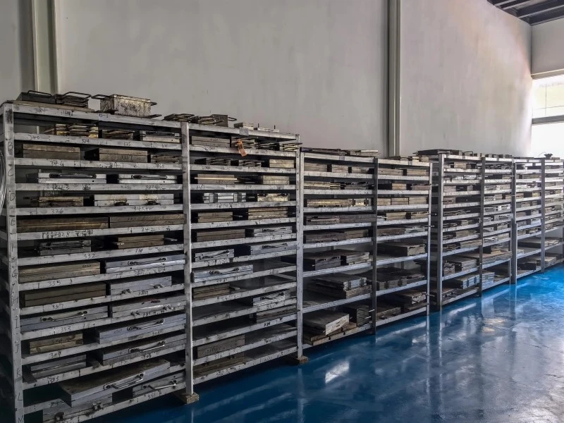
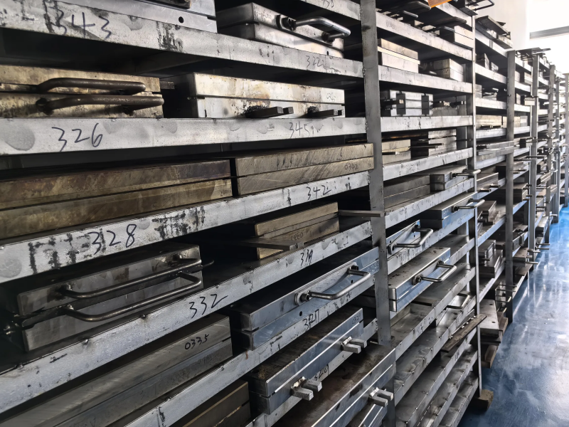
Ningbo Zhonggao provides custom rubber component development support, including UG3D modeling, with a 24-hour model design service and a typical sample lead time of 3–15 days, subject to project requirements. Its engineering resources and existing tooling capabilities can support diaphragm feasibility reviews and prototype development, while the actual process, validation plan, and delivery schedule should be confirmed for each pneumatic valve project.
Learn More About Ningbo Zhonggao
Conclusion
Reliable pneumatic valve diaphragms depend on the coordinated design of effective working area, stroke geometry, clamping edges, rubber compounds, and molding processes. Early design-for-manufacturing reviews and functional prototype testing can help reduce leakage, fatigue failures, and production inconsistencies before full-scale manufacturing begins. Contact our engineering team with your drawing or sample, operating pressure, stroke, working medium, temperature range, expected cycle life, and order quantity to discuss a custom rubber diaphragm solution for your pneumatic valve application.
Find Your Custom Rubber Diaphragms