Introduction
Sending a rough sketch or an incomplete 3D model to a rubber manufacturer often leads to repeated questions about material grades, hardness, tolerances, and operating conditions before the supplier can prepare a meaningful quotation. Missing engineering information can delay design-for-manufacturability (DFM) reviews, create uncertainty in tooling costs, and increase the risk of sample revisions. A complete custom rubber part drawing package helps engineers communicate technical requirements clearly, enabling manufacturers to evaluate feasibility, recommend suitable production methods, and prepare more accurate quotations.
Prepare the 3D CAD Model & 2D Engineering Drawing
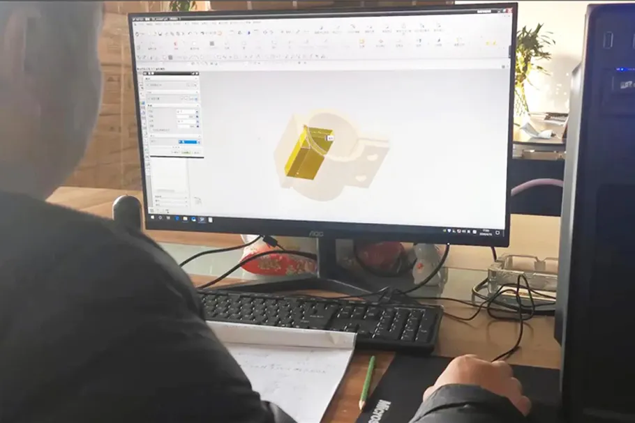
A complete geometry package should combine a three-dimensional model for structural evaluation with a dimensioned engineering drawing that defines measurable requirements and acceptance criteria.
Provide a Neutral 3D CAD Model
- Submit a 3D rubber part CAD model in STEP or IGES format when supported by the manufacturer's CAD workflow, allowing engineers to review the geometry across different design systems.
- Include relevant cross-sections, grooves, wall thicknesses, undercuts, and assembly interfaces so the manufacturer can assess moldability and compare compression molding, injection molding, or extrusion where applicable.
- Provide separate models for metal inserts, mating components, or assemblies whenever these features affect tooling design, bonding, or installation.
Add a Fully Dimensioned 2D Engineering Drawing
- Supply a PDF drawing for convenient review and a compatible editable format, such as DWG or DXF, when required for engineering collaboration.
- Identify critical dimensions, datum references, groove geometry, hole locations, cross-sectional details, and assembly interfaces that determine fit, sealing performance, or functional operation.
- Clearly distinguish critical-to-function dimensions from noncritical features so the manufacturer understands which measurements require tighter process control and documented inspection.
Define Rubber-Specific Tolerances
- Specify dimensional tolerances according to the feature, material, manufacturing process, and functional requirement instead of automatically applying metal-machining tolerances to flexible rubber components.
- Reference ISO 3302-1 where applicable and agree on the relevant tolerance classes with the manufacturer, while defining special limits separately for critical sealing and assembly dimensions.
Define Rubber Material and Application Requirements
Material specifications should describe both the required compound and the actual service conditions, allowing the manufacturer to evaluate whether the selected elastomer can meet the component's performance requirements.
Specify the Rubber Compound
- Identify the polymer type, such as NBR, EPDM, FKM, or silicone rubber, and provide the exact compound grade or material specification whenever it has already been approved.
- State the required hardness and measurement scale, such as 60 ± 5 Shore A, together with the specified color and any relevant appearance or material-performance requirements.
- Include additional requirements for compression set, tensile strength, elongation, abrasion resistance, or other properties only when they are relevant to the component's intended function.
Describe the Actual Operating Environment
- Document the minimum and maximum operating temperatures, contact media, working pressure, static or dynamic loading, and exposure to ozone, ultraviolet radiation, or outdoor conditions as applicable.
- If the material grade has not been finalized, provide an application sheet describing the operating environment so the manufacturer can recommend suitable candidate compounds for engineering review.
Identify Applicable Compliance Requirements
- Specify the applicable market regulations, customer standards, material declarations, and testing requirements, such as relevant FDA requirements for certain food-contact applications or RoHS restrictions where applicable.
- Distinguish manufacturing-system certifications, such as ISO 9001 or IATF 16949, from product-specific compliance requirements, because a certified quality management system does not automatically establish that every rubber compound meets a particular regulation.
Specify Manufacturing & Quality Requirements
Manufacturing notes should define the features that affect tooling, appearance, assembly, and inspection before the supplier finalizes the proposed production process.

Mark Parting Lines, Flash & Functional Surfaces
Identify preferred parting-line locations where necessary and specify acceptable flash limits, gate-mark restrictions, and appearance criteria for sealing surfaces, mating faces, and visible areas.
Explain which surfaces must remain free from unacceptable molding defects and define measurable acceptance limits wherever the component's function or customer specification requires them.
Document Inserts & Secondary Processes
For rubber-to-metal bonding components, provide the insert drawing, metal material, dimensions, positioning requirements, and any applicable bonding-performance criteria.
For die-cut rubber parts, laminated structures, or components requiring secondary machining, include the relevant profiles, thicknesses, interface dimensions, and post-processing requirements.
Define Inspection & Acceptance Criteria
Identify the dimensions, hardness values, visual characteristics, bonding properties, and functional performance measures that must be inspected during sample approval or production.
Specify applicable test methods, inspection reports, first-article requirements, and sample acceptance criteria so the supplier can align manufacturing controls with the buyer's quality expectations.
Check Our Quality Management System
Include Annual Volume & Commercial Requirements
Commercial information helps the manufacturer evaluate tooling investment, production efficiency, unit pricing, and the practical feasibility of the proposed supply arrangement.
State Estimated Annual Usage
Provide estimated annual usage (EAU), initial order quantity, anticipated reorder frequency, and expected demand changes to support a realistic production and tooling assessment.
Explain whether the project requires prototype quantities, low-volume testing, or sustained mass production, since these scenarios may justify different tooling investments and production strategies.
Clarify Tooling & Project Expectations
Request separate quotations for tooling, sample development, and unit pricing where applicable, and clarify whether the project requires a new mold, an existing mold modification, or prototype tooling.
State the target sample schedule, planned production launch, packaging requirements, delivery destination, and applicable Incoterms so the quotation reflects the intended commercial arrangement.
Use a Final Drawing Package Checklist
Before submitting an RFQ, organize the engineering and commercial files into a controlled package so the manufacturer can identify missing information and evaluate the project against consistent requirements.
- Geometry Files: Include the 3D CAD model, dimensioned 2D drawing, part number, revision level, and assembly drawings where applicable.
- Material Specifications: Record the polymer type, approved compound grade if known, hardness, color, and relevant material-performance requirements.
- Application Data: Document operating temperatures, contact media, pressure, loading conditions, and environmental exposure.
- Manufacturing Requirements: Specify critical dimensions, tolerances, parting-line restrictions, flash limits, inserts, and secondary processes.
- Quality Requirements: Define inspection items, test methods, applicable standards, reporting requirements, and sample acceptance criteria.
- Commercial Information: Provide EAU, initial order quantity, target timing, packaging requirements, delivery destination, and applicable trade terms.
- Supporting Documents: Attach reference photographs, existing samples, test reports, assembly information, and NDA requirements when relevant.
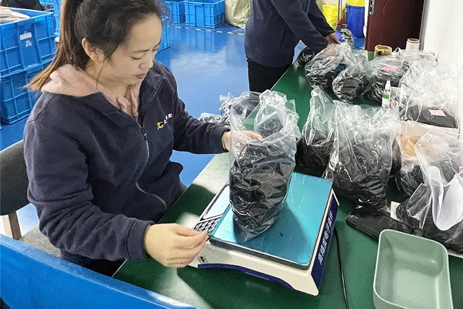
Ningbo Zhonggao supports custom rubber component development with a technical team, mold resources, and a production process that can help customers move from drawing review to sample validation. Its sample lead time is 3–7 days, while the actual development schedule depends on part complexity, tooling requirements, material selection, and the completeness of the submitted specifications.


Conclusion
A complete custom rubber part drawing package should define geometry, critical dimensions, material properties, operating conditions, manufacturing constraints, quality requirements, and commercial expectations in one coordinated set of documents. Providing these details helps manufacturers conduct more meaningful DFM reviews, assess tooling options, identify engineering risks earlier, and prepare quotations that better reflect the project's actual requirements. Send your 2D engineering drawing, 3D CAD model, material and application specifications, annual volume estimate, and target delivery schedule to request a custom rubber part feasibility review and quotation.